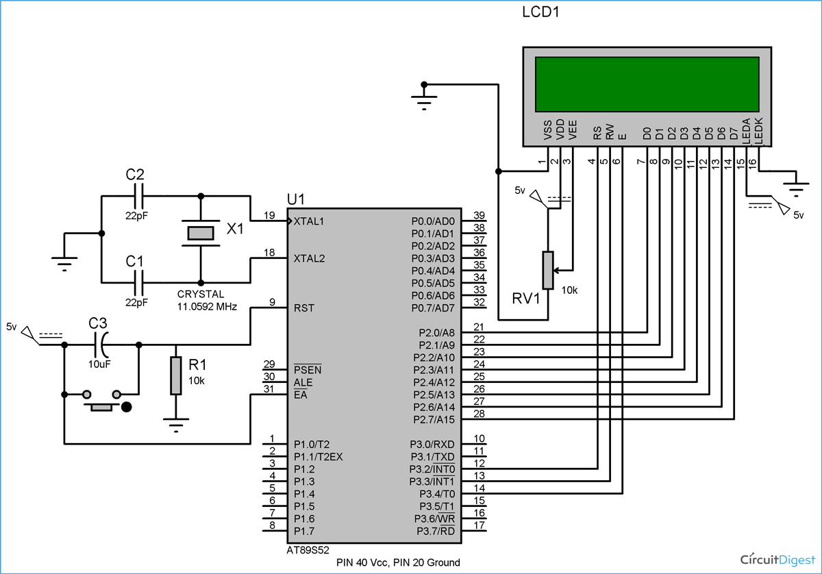
This project demonstrates how to interface a 16x2 character LCD module with an 8051 microcontroller (AT89S52) using Embedded C. It explains pin configurations, control signal timing, hardware setup, and sample code to display text on the LCD.
- Interfacing 16x2 LCD with AT89S52 (8051 MCU)
- Command and data mode handling via RS, RW, E pins
- Full 8-bit data communication (D0–D7)
- Hardware contrast adjustment using potentiometer
- Display static text on both lines of the LCD
| Component | Description |
|---|---|
| 8051 Microcontroller | AT89S52 |
| 16x2 LCD Module | Alphanumeric character display |
| Variable Resistor | 10kΩ for contrast adjustment |
| Power Supply | 5V regulated |
| Breadboard + Jumpers | For prototyping |
| Capacitors + Crystal | For clock and reset configuration |
- Data Pins (D0–D7) → Port 2 (P2.0–P2.7) of 8051
- RS → P3.2, RW → P3.3, E → P3.4
- VSS / GND → Ground
- VDD / Vcc → +5V
- V0 (Contrast) → Middle leg of 10k potentiometer
- LED+ / LED- → +5V and GND respectively (Backlight)
| Hex Code | Function |
|---|---|
| 0x01 | Clear display |
| 0x02 | Return home |
| 0x06 | Increment cursor |
| 0x0C | Display ON, cursor OFF |
| 0x80 | Force cursor to beginning of first line |
| 0xC0 | Force cursor to beginning of second line |
lcd_cmd(): Sends commands to LCDlcd_data(): Sends characters to LCDlcd_init(): Initializes LCD with command sequencemsdelay(): Generates millisecond delay using nested loops
Text display is handled in a loop using lcd_data() and string iteration until a null character ('\0') is reached.
| Issue | Solution |
|---|---|
| LCD shows black boxes | Check contrast (adjust potentiometer) and +5V supply |
| Garbage characters on screen | Verify data pin wiring and initialization command sequence |
| LCD not responding | Check RS, RW, and E logic and timing |
| Scrambled characters | Increase delays, ensure proper command/data switching |
-
Why is my LCD blank?
→ Check VDD and contrast pin connections. Ensure LCD is initialized withlcd_init(). -
What are essential commands?
→0x38,0x0C,0x01,0x06,0x80,0xC0. -
Can I use 4-bit mode instead?
→ Yes, to save pins, but this project uses 8-bit mode for simplicity.
- 📖 Full Tutorial on Circuit Digest
- 📘 16x2 LCD Datasheet & Pinout
- 🔌 LED Interfacing with 8051 (Beginner's Guide)
- 📚 More 8051 Projects
- 🟩 Interfacing 16x2 LCD with Arduino
- 🔵 16x2 LCD with Atmega16 in 4-bit Mode
- 🟠 16x2 LCD with ARM7 LPC2148
Built with 💡 by Circuit Digest
Making Electronics Simple
8051 LCD interfacing AT89S52 LCD code 16x2 LCD tutorial lcd_cmd lcd_data
8051 embedded C 8-bit LCD mode RS RW E enable timing
microcontroller lcd communication lcd contrast potentiometer


